Sunday, August 18, 2013

The Harmony B3500 Bass Amp

Here's a little bass amplifier I picked up for pocket change: A late 70's solid state bass amp, the Harmony B3500, with a matching cabinet. For reasons unclear to even me, I'm inordinately pleased with this little thing. It's apparently somewhat rare--at least in working order. I haven't unearthed any web photos or documentation.


So the specs are rather unclear, but I can make some educated guesses:

-- B3500 is the retail model number.
-- 7044B-90PB is the factory model number.
-- 35 watt output (EDIT: maybe not. Sucker is loud for a SS amp, could be 50w).
-- Came with optional matching cabinet, 4 or 8 ohm load (Speaker complement? I'm thinking 1x15).


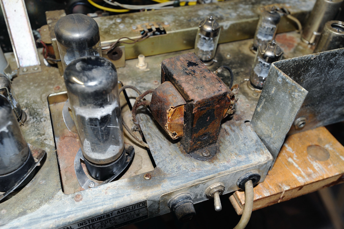
The wattage guess should be accurate--the back label lists the total power consumption at 50 watts (of course output must be lower), while the name itself--B3500--strongly suggests the likelihood of 35 as the magic number. (EDIT: again, rethinking this...might have to hack test the wattage...)

And the speaker load? Harmony sold a sister amp--the L3500--for guitars ("L" for Lead, no doubt). The L3500 had tremolo and reverb, and likely an identical output stage. References to that amp can be found online. Unfortunately they differ as to the cab impedance; sources list both 4 and 8 ohms. One source lists the cab as 2x12, but it's dimensions make that a very tight fit...

The cabinet is missing the original speaker and baffle board, but it's likely from it's size that the original complement was one 15'' speaker. It came with a poorly fitted homemade baffle and a Quam 12C16MI guitar speaker. "MI" for Musical Instrument speaker; apparently Ampeg used them in guitar amps in the late 70's, early 80's. It's painted gold and I have two. I'm fairly curious as to their sound in a good guitar cab. I have a 1950s Quam speaker in my Lectrolab R600 which has a very cool sound, but it has only fair efficiency--not surprising really, for the era.

The cabinet certainly belongs to the head--the width and tolex are identical. For now an old 100 watt Utah 15'' speaker will be fitted to the cab.

It's clearly dated to sometime in 1979. Here's the back of the head. I've redacted the actual serial number, but it's in the 05xxxx range.


As a Harmony product produced in 1979, this amp originates in a "shadow period" of company history. Harmony ceased operations in 1975. Originally founded in by Wilhelm Schultz in 1892, Harmony functioned continuously as a business until that year. Post 1975, Harmony seems to have undergone several incarnations--reportedly as a brand name for Asian-made musical instruments and accoutrements. However, there were a variety of owners and management over a 25 year period until 2000. At that time the name was acquired by M.B.T. International. The Harmony brand was purchased by the Westheimer Corporation in 2009, it's currently owner / operator.

Any additional information about the company during the era of these amplifiers (1979-1982) would be appreciated...

The internals are compact, as early solid state amps often are. The output stage is an NPN / PNP push-pull pair.


Note the fancy script "T" on the PCB. My old 70's Thomas Organ wah pedal has the identical manufacturers mark. I need to track that down...

Despite my dearth of experience with bass amps (I haven't really played bass since the early 70's), I find myself really liking the amp. I acquired an old Peavey Forum bass a couple years ago and it sounds very nice through the B3500--much better than running it through any of my guitar amps. It's punchy but not distorted (up to 9, anyway--and maybe that's 'cause I'm using a guitar cab until I fix up the Harmony cabinet). Sure, it's not loud enough for a rock setting, but it's not too quiet either. 

Anyone else have a Harmony B3500? Or use one back in the day? Drop me a line...

Thursday, July 25, 2013

Farmers Insurance is...not so bad (was "worthless crap")

 Two weeks after the accident, I gotta say that "Farmers Insurance" dealt with us fairly honorably, although the claims representative was--not so great through the experience. If I hadn't found a service center and secured a rental myself, who knows how long it would have taken?

In the end, Farmers fixed my car, and they paid for the full rental. I suspect the complaints account on Facebook was a big help.

We were able to visit my ailing Uncle Don in MA pretty much as planned (delayed by one day), and that was the primary reason for the trip. So that was good. Given my uncle's health, I doubt we'd have been able to schedule a trip until late this year, and who knows?

The original post is below:

---------------------------------------------------
Yesterday (Weds, 11:30AM) while at a dead stop in a road construction zone, I was rear-ended by a driver who carried Farmers Insurance. Today we were leaving for a trip to Massachusetts, to visit family and see my uncle, who's in hospice.

2:30PM, Thurs:

27 hours and seven phone calls later, I finally spoke to the claims representative. They tried to contact me once with wrong number yesterday, although I had left them two separate phone numbers, on three occasions... Yet when I called the claim center at 12:30 PM today, their automated system already knew who I was (I'd called yesterday). But when I called back two hours later at 2:30PM, the system no longer knew--the rep had apparently reset the number, rather than use a number that that the automated system had shown to be correct. That second call to the center (today; third total) finally connected me to the representative.

So get this--they accept the responsibility for the accident. But because I was able to drive my vehicle away, we're not eligible to receive a rental. So we're delayed possibly for days while we resolve this issue.

My vehicle is in better shape than the other driver, but the bumper is trashed and the exhaust system looks sketchy. We certainly don't want to drive it 1400 miles.

The moral: DON'T DEAL with FARMERS INSURANCE--if you possibly can avoid it.

Update 1, 3PM Thurs.--I'll keep posting as the farce continues. Now I'm waiting for a response regarding repair options...which they said would be included in an email, but were not... 

Update 2, 4:21PM Thurs.--the Farmers Insurance website sent me a document telling me that my claim was "inactive" until I get an estimate...but the web document could only be accessed by giving the incorrect phone number. And of course neither the representative or the supervisor has responded to my request to clarify a repair location--maybe because they're using the wrong number, even though I've given them each the correct number via phone, and email.

Update 3, 4:40PM, Thurs.--The staff at Farmers has been unresponsive, but their website at least has authorized service locations. I found a helpful person at a local shop, and can take my vehicle in without an appointment. Too bad it's too late for an estimate today...

Update 4, 6:10 PM, Thurs--Receive an email from the claims rep, saying they cannot contact me via phone. The phone number they quote is the same incorrect number they've been calling for a whole day. Even though I'd verbally given the same rep the correct number @ 2:30PM this afternoon, and emailed the correct number at 4:15PM.

So day two ends without resolution.

But my wife contacted Farmers via Facebook, where they have a complaints account. 

Friday Update

Took the vehicle early this morning to the authorized repair center. They were very helpful. They sent us on to the rental agency.

At the car rental we were informed that Farmers would only pay for the days while the car was being repaired. We expected this. But at this point we were a day behind schedule, so we didn't care. We got the rental vehicle and went home to continue packing for the trip.

At 10:15AM I called the claims rep, who had indicated the night before her intent to contact me. But she didn't even try Friday morning. By some miracle I got through. She was pleased the car was at an authorized center (sure--I did all the work), and seemed more sorry for the person who's number she kept calling, rather than my own correct number. I don't have a clue why she didn't try to call me Friday morning, as she'd indicated.

We left town and stopped my mother-in-law's house for a couple hours before leaving OH. Sometime during the drive I received a couple phone calls from their complaints people--probably prompted the Facebook msgs--but we didn't hear the phone in the car.

At this point, I didn't care. By 2:00PM we were on the road, next stop New England, via PA. 

If we had to pay for part of the rental, so be it. I was freaking sick of dealing with them.

Tuesday, June 11, 2013

Electro-Harmonix Holy Grail Rev A photos

As promised, here are photos of the Electro-Harmonix Holy Grail PCB board (Rev A), from the populated side...otherwise known as "the top." Yes, "Rev A" means the first release of the Holy Grail Reverb pedal.

In time I might even document the wire connections, which are labeled with individual letter codes.


They do make cool stuff...

The first Holy Grail post on Redplate City, with more photos etc., can be found here.

Friday, May 24, 2013

Teisco Checkmate 60--A First Look

Busy times--too many distractions prevented me from posting about the vintage Teisco Checkmate 60 amplifier. But here it is, in all it's worn glory. I'll keep this post mostly a preview, and not include too much detail...

First off, two of the front-panel knobs are missing. It's easy to spot the "stunt knobs" in the photo. The front panel itself is very clean. The tolex is decent.


Here's the back. Sorry, these aren't glamor shots--not enough free time currently. But decent enough resolution, compared to any other web photos.


It's not perfect. Plenty of imperfections. A coating of mouse piss (or is it?) inside to clean up. Some rust, too. The handle is missing.

Let's be straight, right off. The one significant disappointment is the output transformer, which is non-original. More--MUCH more on this later.

But it works, as-is. EVERYTHING works--reverb, tremolo, both channels, all the switches. Even the replacement OT works. Again--more later. And it sounds GOOD.


Whaaa.... That's pretty nasty. Note that some of the crud has already been scraped off the chassis. Luckily, the underside "guts" of the chassis are pretty clean. The chassis itself has an unusual in-cut or inset corner (on right of the photo). On the inset are jacks for the reverb and tremolo footswitchs. The high corner steel panel in the inset is unusual, too--maybe the footswitch and cable tucked into the inset for storage. For some reason, the steel panel has been bent and will need attention.


No way! That's NOT an output transformer for a 60 watt pair of EL34s in push-pull configuration. Nope, it's only attached with one screw--it's too small to reach the second hole in the chassis. The original was definitely larger. But it does provide proof-of-functionality (again, more later). 

The residue around the OT is wax, probably from the current or the previous transformer, which was likely potted. Since the original is gone, it's the primary suspect.

By the time I'm writing this, I've made progress. This amp is COOL.

Specifications

Here's a chart of the chassis, top side. The tubes and major components are labeled. There are four 12AX7, two 12AU7, and a 5AR4 rectifier. There are three multicaps, a reverb tank and the reverb driver transformer.


Power tubes? The Checkmate 60 uses a pair of 6CA7 tubes (EL34). I suspect this IS the original power tube complement. Other sources reference a pair of 6L6 tubes, but I offer as evidence a blurry enlargement from the '68 catalog:


While it incorrectly lists only one (two are required for 60 watts), it clearly does reference the 6CA7, which wouldn't be used in a guitar amp for anything but a power tube (there's also something X 2, but it's nearly illegible--might be a measurement, almost looks like "30cm"). The two power tubes are mounted on a small "daughter board" set into a rectangular hole in the chassis.

The back panel image is below. "Tremolo" and "Reverb" are footswitch jacks. The rest is self-evident. There's some weirdness with the speaker jack wiring, but I'll detail that in a later entry.


Incidentally, a historical Yen-to-USD online calculator indicates that 90,000 yen in 1968 equals $889.90 USD (or 687.98 EUR). Adjusted for inflation, that converts to a value in 2013 dollars of $5,946.25. For both the amplifier and the cabinet, of course. If purchased separately, the cabinet was 32,000 Y, about 35% of the total. You do the math...

Wednesday, May 1, 2013

Teisco Checkmate 60 amp arrived

A vintage Teisco Checkmate 60 amplifier landed on my doorstep yesterday. It's a flea-bay purchase from a seller in Kentucky. No photos yet; here's one from the seller:


It's circa 1968 or 1969--the Checkmate 60 is listed in the 1968-69 Teisco catalog, along with the May Queen. The catalog page has been floating around the web for years--my thanks to whomever scanned it originally.


More photos and documentation to come.

It's pronounced TAY-sco, BTW...

Thursday, March 28, 2013

Cleveland Romper Room organ for sale

A piece of Cleveland baby-boomer history is up for sale: the organ used on the Cleveland production of Romper Room (allegedly) is currently on Craigslist. The seller is based in Euclid, a suburb of Cleveland (for any non-NE Ohio folks).

Here's the link:
http://cleveland.craigslist.org/msg/3702311343.html

The listing itself is rather matter-of-fact:

baldwin organ $49 (euclid) pic

This organ was originally used for Romper Room. Needs repair and some tlc. It powers on but the actual organ pitches need tuned. Will take trades also. Call 216 406 1699 

(A screen capture is below; all CL ads are transitory..)


Romper Room was a long-running children's television program shown mostly in the USA, but also internationally. It was notable because cities could host individual franchises instead of the national broadcast. Cleveland hosted a local production, starring "Miss Barbara" Plummer. While not the first Cleveland hostess, "Miss Barbara" will always remembered locally as the face of Romper Room; the highlight of the production which ran on WEWS from 1958 until 1971.

Tell me, tell me, tell me, do. Magic mirror, tell me today.
Have all my friends had fun at play?


As crude as TV F/X were in the early 60's, the Magic Mirror closing sequence of RR is probably the first TV special effect I remember from my childhood...

So any Do Bee out there with enough living-room space can purchase a bit of local broadcast history...

Friday, March 22, 2013

A Still from "Olympus Has Fallen"

Here's a publicity still from the new action movie, Olympus Has Fallen, starring Gerard Butler.


Wow, that just looks crazy good; I bet it's an intelligent, tightly-crafted thrill-ride...

(Original image by Tom Freeman. More info here...)

Sunday, March 17, 2013

Google News algorithm sucks

Less than 12 hours after the Steubenville rape trial verdict, my Google News page/feed--yeah the one that's supposedly customized to the "individual preferences" of the reader--shows no links or references to the case, one of the biggest stories of the day. Not under the "Top Stories" nor the "US" sections.

To be sure, Google isn't my main source of news. We subscribe to, or read, up to five newspapers a day, depending on the day. I don't use my real name on any Google services, and don't intend to.  I'm fairly serious about using ad-blocking and script-blocking when I browse, so I am harder to "data mine."

And Gmail? It's just a disposable alternative to my normal email account. You know--the one you use for Craigslist or when you're required to enter an email address online. I have Google+ account, but won't use my real name, of course (don't bitch Google--I'm not even on Facebook). So again, I'm resisting their profiling efforts, at least a token amount...

Still--honestly--how bad is an algorithm when it can't recognize I might be interested in this type of news? ...especially when I personally customized my page by modding UP the New York Times and modding down Fox.

But beyond that--shouldn't we all be reading about the Steubenville verdict? Why is Google News (or ANY news source) so bent on giving me only the news they think I might want? Yes, I know the answer-- $$$$$ rule. 

We need a return to the traditional paradigm: one where actual editors define the news mix, one based on common humanity, solid news judgement and informed experience.

Friday, March 15, 2013

Old-School Danelectro Logo SVG

A year or so ago I picked up a Danelectro DM 25, in need of much repair. After replacing a few components it works quite well, although it's missing the peizo reverb tank.

But the front panel is a mess...


I'll have to make up a replacement. This can't be salvaged.

To that end, I photographed the old Danelectro logo on the front of my Dano DM10, an amplifier that's contemporary to the DM 25. The DM 10's condition is much better. Even so, there's plenty of corrosion evident on the smaller amp. It's not enough to warrant replacement, though.


This image file was then imported that into Inkscape, a great freeware vector image editor. Inkscape has a powerful autotrace function for bit-mapped images which is super useful for converting photos into vector format. After a little tweaking, here's the result, which is very true to the original:


The old-school logo isn't quite the same as the modern one. It's a little rougher, a little more vintage. The above image is a JPG file, but I'm glad to share the vector file for other users:

Danelectro Logo, SVG

This link will display (at least on Firefox), but download Inkscape to edit or resize it. Remember--it's a vector file, so there's no pixellation when enlarging... Enjoy!

Sunday, March 10, 2013

I Heart Pedal Trading; or Quieting the EH Holy Grail Reverb

Yesterday I traded a DiMarzio "Very Metal" pedal for an Electro Harmonix Holy Grail Reverb pedal, the EH power supply included. It's the original "wide" model (and has Rev A on the PCB). I'm excited to have a compact reverb, for use with those amps that don't have it. My Lafayette "Echo-Verb" is cool, but it's big and needs maintenance (bypass get's muddy when the effect is set over halfway--probably needs new caps, or just a relay-driven bypass).


I love trading gear. Everyone wins--you clean out unused and unwanted stuff, and replace it with (hopefully) stuff you want, and might actually use. I never used the Very Metal pedal; it's really not my sound. Plus the non-true bypass wasn't very transparent. Yeah, it looked ironically cool, and probably will continue to be collectable, but that's mostly based on the famous "knobs that go to 11." But I generally only keep things I use; if it sits, let someone else enjoy it.

I crack open the Grail to check the type of bypass--and find it's a true-bypass version. Some of the first versions didn't have it. I don't know if it was home modded or factory, but I'm happy... 

True bypass

Oh the Noise Noise Noise!


Plug in the Electro Harmonix power supply, and the Holy Grail works fine. However, it's noisy, especially set above halfway. Overall, I'm somewhat disappointed with the noise floor at such a noticeable level. I half expected this from online comments. 

What do we suspect first with noisy digital pedals? --the power supply. The original EH power supply is a standard step-down transformer/rectifier type, a likely culprit.

So I try the Holy Grail with a 1Spot switching supply, daisy-chained with other pedals. Cool! It's much quieter! But when the Cry Baby wah is engaged there's a very noticeable high-pitched whine as the treadle is pushed down toward the treble position. Not good.

Next option: use a second 1Spot, dedicated to the Holy Grail alone. I keep a second 1Spot on hand to use with effect loops. Success! The Holy Grail is whisper-quiet, and now some of the subtleties of the effect can finally be heard.

You may take this as gospel ;-) -- always use a separate, dedicated switching power supply for the EH Holy Grail Reverb pedal.

Using a 1Spot with the Holy Grail requires an adapter cable to fit the 3.5mm jack. FYI, the polarity is fairly standard--shaft negative, tip positive, +9V. Ironically, I had the adapter already, for the Very Metal.

Overall Impression of the Electro Harmonix Holy Grail Reverb


I like it a lot. It's smaller than an external spring reverb. It does a decent job of simulating reverb for amplifiers that don't have the option. I can't say I LOVE it, but then I'm spoiled by the real thing...

The Hall setting is particularly good, if not something that I'd use often, or use live. But it's very cool. 

And the Flerb setting? (Flanger/reverb)--it's great fun! Again, maybe not a "live" effect, but cool anyways.

Goodbye "Very Metal"


Here's portrait of the DiMarzio pedal. Very Metal, I hope you've found a home, but I won't miss you...(except for your knobs that go to 11).

I got you in a previous trade for the equivalent of $25, and I traded you for something I wanted...more. Pedal love is fickle...


EDIT:
After further testing, a tiny amount of high frequency noise is still present with the dedicated 1Spot. But it's very small compared to the hiss and whine of the other options...

Wednesday, February 27, 2013

Adventures in Walking #1

Did two loops of the Hudson Springs Park trail today in the rain, about 4.2 miles total. With temps hovering around 39 F, it's a grey, dreary day.

One highlight--a dude playing Frisbee golf in the cold rain, rocking the hair. Brilliant. Reminded me of the guy in the Allstate commercial ("It's like we're connected"). 

He even stopped to wave. Outstanding.

Saturday, January 26, 2013

Peavey Ultra Plus Resonance circuit


Unlike the newer Ultra Plus amps, my Peavey Ultra 60 amp project doesn't have a NFB resonance control. I could experiment with any NFB loop filter, but why not start by reversing the Ultra Plus circuit? There isn't much info available on it, so it makes for a little detective work...

The Ultra Plus resonance control is a three-position switch type, labeled TIGHT, MED and LOOSE. The filter setting are preset at the factory. There's no adjustable POT like some resonance controls utilize.


One fact is known from the start--the Ultra and the Ultra Plus are VERY similar in nearly all aspects. The point on the phase inverter--where the feedback is routed--and the transformer tap (the 8 ohm secondary) are identical in both amps. The Ultra Plus merely adds some addtional components between the two points.

Off to the web to research. First off, it looks like Peavey went to some length to hide / obfuscate the feedback loop circuit. There are versions of the Ultra Plus schematic that omit both the feedback control schematic and it's small circuit board, too. And some experienced Peavey Techs even commented on that fact on the interwebs. There's also a little note on the "sanitized" schematic how "THIS CIRCUITRY IS PROTECTED BY U.S. PATENT NOS..." bla bla bla. Look up the patents if you wish, they are easily found. The 5,197,102 patent seems somewhat applicable. But I don't see anything groundbreaking there (i.e., anything unique) that applies to the Ultra Plus resonance circuitry... 


After more searching, eventually I did find a schematic with the NFB loop filter intact:


OK--for all the fuss, it's not a very complicated design. And not that different from other NFB filters, such as the Fender Bassman AC568 for one, and several older Gibson amps.

But the switch diagram and the switch description are confusing. The switch, tagged S3, certainly looks like a standard DPDT switch on the schematic, but the parts list says SPTT (or Single Pole Triple Throw). The drawing is not a single pole switch in the normal sense. More obfuscation, or just in-house terminology?

Moreover, it doesn't "decode" correctly as a standard DPDT switch, either. That is, it wouldn't function correctly using a standard switch. Too bad I don't have an Ultra Plus to poke around it's insides...

After several failed sketches and more research, I found the best candidate for the switch; a DPDT on-on-on switch, where the contacts on each pole are opposed in the middle position. It works like this:


(Of course, one wonders why this isn't termed a DPTT switch...)


Anyhoo, with this type of switch all three functions work correctly (as I read the schematic). If you'd rather not trace the paths yourself, I drew each setting individually:


Position 1) bypasses C10
Position 2) parallels C10 with an 82K resistor 
Position 3) parallels C10 with a 330K resistor

(..there's also a 68K resistor between the filter and the PI, as noted below..)


And that's the resonance control for the Peavey Ultra Plus. Could this be added to the Ultra 60 and Ultra 120? Sure! To replicate it exactly, order the switch from Peavey directly.

Can it be modified? Yup, easily! Replacing the switch and the fixed resistors with a POT, say 500K or 1 Meg would work. The bypass switch would effectively remove the resonance circuit completely, which would be a "stock" Ultra 60 NFB loop.


For comparison, below is the resonance / presence circuit for the Peavey 5150 ii. I've drawn a simplified version--this amp has dual controls, one for the clean and one for the lead channel, and the image below has been reduced to a single set of controls.
 

Note that the Peavey Ultra (and the Plus) has a fixed feedback resistor of 68K in the loop between the transformer and the phase inverter (and the Ultra Plus inserts the resonance control between the resistor and the transformer), while the 5150 has a 39K resistor between the transformer secondary and the filter circuitry, probably due to the addition of the Presence control--or the different sonic characteristics of the amp itself.

So if adding both Resonance AND Presence is your thing, give it a go...

One additional note: the aforementioned patent (5,197,102) seems more applicable to this circuit than the Ultra Plus... But I'm no lawyer, of course, so don't take my word on it.   Wink.


Keith Richards arrested for stealing Telecaster (wink, wink)

Keef, No!

And things were going so well...

OK, not that Keith Richards. From the Crime Report in today's Record Courier daily newspaper, Portage County, Ohio, Jan. 26, 2013:

Keith L.Richards, 22, with a last known address of 8937 S.R. 88, was arrested Jan. 22 and charged with theft, a first-degree misdemeanor. Richards allegedly stole a Fender Telecaster electric guitar from its owner on July 31, 2012, with intent of selling it, according to the Portage County Sheriff's Office.


The RC Crime Report is pay-walled so I can't provide a direct link, unfortunately.

Saturday, January 12, 2013

Some Cool Guitars (Part One)

Here are a few of my guitars, at least some of the funky ones. I have others guitars that are more ...functional... and modern, of course, but these are great fun.

The first is a Norma "Barney Kessel" model. It doesn't actually say that on the guitar, but a prominent website that features vintage guitars (My Rare Guitars) refers to the guitar by that name. Quote: "A very rare Norma split p/u Barney Kessel design." His guitar is black, and I don't see a bridge cover in the photo; otherwise they are twins. It has a big "baseball bat" neck, but it's a blast to play and it's great for a rockabilly type sound. The split-pickup setup is pretty unusual, and actually functional.

It has another cool feature--there's an inductive "varitone" type filter built in to it. It uses a small transformer as the inductor. The filter switch (L,M,H) is down near the lower (and oddly placed) F hole cut-out. It might be a resonant filter (should be), but it sounds like a high-cut to me.

Norma Barney Kessel
The Norma "veritone" inductor and switching for the split pickups

The split pickup switching plate for the Norma


The green burst is my Sekova--coolest headstock ever! 


Next is a red-burst Kingston thin-line hollowbody guitar. It has gold-foil pickups and an extra long tremolo bar...but it feeds back like mad. Looks cool, but wouldn't play it above living room levels.

Kingston #I
 
This violin style Kingston is a surprisingly great guitar! The action is excellent, the intonation good and it has a cool voice.  

Kingston #II


Two project guitars--a Kimberly Phantom 22 thin-line longhorn model. This guitar has the same pickups as a Teisco May Queen, and the tremolo and bridge also are the same. That's gotta say something about the date (and location) of manufacture. The other is a Maxitone something or other. Someday I'll finish fixing both up. 

The Maxitone is a step up from most MIJ thin-line guitars. It's definitely heavier, more solidly built. Another with a uniquely weird headstock. I tried fixing the one bad pickup, which kinda worked, but was too noisy. Haven't found a replacement yet...

Kimberly Phantom 22 and a Maxitone


All the funky tremolos work fairly well on these MIJ oddities / beauties. Better than many stock Fender-style trems. Not the thing for dive-bombs, but still pretty cool.

Finally, here's an unbadged lap steel but I think it's a National. That is, I've seen identical guitars advertised as such on the 'bay.

National lap steel (?)

Peavey Footswitch Conversion--Triumph to Ultra

Converting a Peavey Triumph footswitch to a functioning Peavey Ultra 60 footswitch

After trolling ebay for a Peavey Ultra footswitch, and realizing the cost would be somewhere between $50 and $85, it was time for the DIY route.

I had one advantage--I'm the semi-proud owner of two Peavey Triumph footswitches; someday I'll detail the "tale of two Triumphs." Both are the 6 pin DIN type (the Triumph PAG uses the same schema as the Ultra, but I'm not that lucky). Might as well use the one with the broken Switchcraft DIN plug...


Busted Switchcraft plug

Some go-getter added big stick-on labels to the switch...


The Triumph and Ultra FS layouts are identical: three switches, four LEDs and the functional setup is the same. But the Ultra uses a 7 pin DIN connector, while the Triumph is the 6 pin DIN type. 

I crack it open, and I'm happy to discover another bit of serendipity--while the Triumph connector is 6 pin, the cable itself has seven wires, and one is unused. Nice. So converting it to the Ultra 60/120 footswitch is very do-able.

Here's the original wiring. Note the current-limiting resistors for the LEDs. In the Ultra series, those resistors are in the amplifier itself, not the footswitch. Also, note the unused red wire zip-tied to the cable...


Original wiring
The wiring conversion in the footswitch itself was super easy. There are several documented Peavey footswitch diagrams on the web. Here's one that was very helpful. I've converted it to an image, but the original is a PDF, and you can find it if you look...


And here's the FS rewired. I've clipped out all the resistors, and wired the switches, LEDs and wire colors exactly as shown in the diagram. The switch tabs in the diagram correspond exactly with the footswitch itself. Even the colors of the LED wire leads (red and black) correspond:


Converted to seven pin, Ultra style

But that's only half the story. I ordered several 7 pin male DIN plugs, courtesy of an ebay supplier. Obviously, these go on the end of the cable.

In conjunction with the wiring diagram above, I've added a drawing with the color codes for DIN pin connections. The colors correspond with the wire colors internal to the footswitch--assuming the switching diagram is followed exactly. The wire to the ground pin (4), labeled "common" below, doesn't have a color; it's unclad stranded wire. This drawing made wiring the plug easier for me; maybe it'll help someone else:

Ultra DIN pin wire colors

Helpful tip: don't buy cheap ebay DIN plugs. These things are the devil to solder. I gave up the first time. While the solder side ends have small recesses for the wires, they aren't of a consistent depth...and the plastic pin holder melts easily.


Tiny, inconsistent soldering recesses

Cheapo DIN plugs
So save yourself the headache and buy good Switchcraft DIN plugs. It's worth it. I eventually succeeded, but it took plenty of flux, a lot of squinting...and swearing... Sorry, there's no photo of the finished plug. Once it worked I was reluctant to disassemble it for a photo. 

I'm psyched to have all three channels functioning, and the reverb switch working as well. The clean channel on the Ultra is beginning to grow on me. And I'm hearing the "Crunch" channel for the first time. It's cool! You can really dial it down to contrast with the "Ultra" channel. Great for bluesy stuff. Or punch it up for a more Marshall-y sound.

I have doubts as to the "robustness" of the connector, and I don't think it would last long while actually gigging. But if it comes to that, I'll buy the Switchcraft plug.

Oh yeah--Helpful Hint #2: Save yourself some grief; the "Channel" button must be pushed, or the footswitch won't function correctly. I read that in the Ultra manual (online at Peavey.com)...as a last ditch effort to discover why the pedal didn't work...after about two hours of aggravation.

Also, I did find a nice DIN plug locally (at Philcap electronics) and it has the larger solder collars on the pins. It's not Switchcraft, but it's an older MIJ part. Mid priced--about $4.50 USD; maybe half the cost of Switchcraft (minus the shipping). I'm holding it in reserve, 'cause the current plug is bound to fail...